- +86 18120750932
- colin@xmsinuowei.com
- th.xmsinuowei.com
The multi-layer ceramic capacitor (MLCC) is one of the most common capacitor varieties found in electronic design. It offers a wide range of bulk capacitance and voltage tolerance in numerous form factors at relatively low cost. While these devices have become commonplace in the designers’ tool chest, they exhibit some often overlooked peculiarities.
Of primary concern is the sensitivity of effective capacitance to several environmental factors, including temperature, applied bias voltage, and age. If these factors are unaccounted for, the risk of product failure becomes very real, especially in manufacturing variability and overall tolerance stack-up.
MLCC Temperature Considerations
MLCC’s are typically divided into two classes based on the type of ceramic material used for the dielectric. Class I capacitors are the most robust with the fewest sensitivities and are usually built from TiO2. A three-letter EIA code is used to classify the temperature coefficient (TC) in ppm per degree Celsius, a multiplier, and a tolerance. Class I capacitors are often listed as C0G, which is the lowest of all temperature sensitivities, implying a -55°C to +125°C temperature range with a capacitance change of ±30ppm/°C and total capacitance varying less than ±0.3%.
Class II capacitors are typically constructed from BaTiO3 dielectrics and provide a much wider range of bulk capacitance at the expense of higher temperature sensitivity. The commonly used Class II devices are X7R, Y5V, Z5U. Table 1 presents the EIA codes and corresponding values for temperature coefficient and capacity range.
Using Table 1, a few examples are shown below:
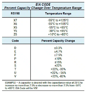
Table 1. Ceramic class dielectric EIA code
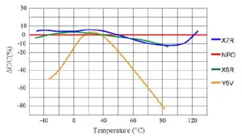
Figure 1 – Change in MLCC capacitance versus temperature for different EIA codes
Figure 1 depicts the change in capacitance across the entire temperature range for several different EIA coded MLCC’s. Knowing the environmental conditions in which a capacitor operates and understanding the design’s tolerable variation can be critical to proper functionality. For example, in a high-temperature application, picking a low-cost Y5V device instead of a more appropriate X7R device would all but guarantee its failure.
DC BIAS Voltage Impact to MLCC Capacitors
Another inherent sensitivity of MLCC capacitors is the change in bulk capacitance with applied DC bias voltage. For example, as shown in Figure 2, the larger the applied DC voltage, the smaller effective capacitance. The capacitance in this example drops by approximately 45% at 25V, which is only half of the device’s 50V rating.
The origin of this phenomenon is the crystal structure of the ceramic dielectric. With no DC voltage applied, no electric field is present, and the crystal dipoles will arrange themselves randomly throughout the device. This scenario is referred to as spontaneous polarization and results in a high dielectric constant and, in turn, yields high capacitance.
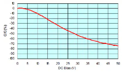
Figure 2 – Change in capacitance versus applied DC voltage for an automotive X7R 50V MLCC
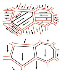
Figure 3 – Crystal polarization without (top) and with (bottom) applied DC bias voltage
เมื่อใช้แรงดันไฟฟ้ากระแสตรงต่ำ สนามไฟฟ้าจะทำให้ไดโพลบางส่วนเรียงตัวขนานกัน ดังแสดงในรูปที่ 3 การจัดตำแหน่งของไดโพลกับสนามไฟฟ้านี้จะทำให้ความจุไฟฟ้าลดลง เมื่อใช้แรงดันไฟฟ้ากระแสตรงมากขึ้น ไดโพลจะเริ่มเรียงตัวมากขึ้น และความจุจะลดลงอย่างต่อเนื่อง เมื่อถึงแรงดันไฟฟ้าที่กำหนดแล้ว ระดับความจุจะลดลงมากถึง 70% จากค่าเล็กน้อย โดยเฉพาะอย่างยิ่งอุปกรณ์คลาส II ได้รับผลกระทบจากสิ่งนี้เนื่องจากโครงสร้าง BaTiO3
เช่นเดียวกับในกรณีของความไวต่ออุณหภูมิ การตระหนักถึงการพึ่งพาแรงดันไบอัส DC สามารถมีอิทธิพลอย่างมากต่อการออกแบบ หากใช้ MLCC เพื่อกรองสัญญาณ AC ขนาดเล็กที่มีส่วนประกอบ DC น้อยที่สุด ตัวเลือก MLCC ต่างๆ อาจเหมาะสม หากการออกแบบกรองการกระเพื่อมจากตัวควบคุมกระแสตรงแรงดันสูงแทน MLCC อาจไม่ใช่ตัวเลือกที่ดีที่สุด
ปัจจัยสำคัญของการพึ่งพาอคติ DC คือความหนาของอิเล็กทริก เมื่อไดอิเล็กตริกหนาขึ้น ความเข้มของสนามไฟฟ้าจะอ่อนลง และการลดความจุจะน้อยที่สุด ดังนั้น เพื่อลดผลกระทบของ DC bias ผู้ออกแบบสามารถใช้เทคนิคต่อไปนี้:
MLCC อายุ
วัสดุไดอิเล็กทริกที่ใช้ใน MLCC ระดับสูงเพื่อให้ได้ความจุสูงต้องทนทุกข์ทรมานจากกระบวนการชราโดยธรรมชาติ ตาข่ายคริสตัลของวัสดุเหล่านี้มีพลังงานความเครียดในตัวซึ่งก่อให้เกิดไดโพลไฟฟ้าถาวร เมื่อเวลาผ่านไป ความเครียดนี้จะผ่อนคลายลง และความจุจะลดลงอย่างช้าๆ
รูปที่ 4 แสดงตัวอย่างอุปกรณ์ X7R และ Y5V ที่มีอายุมากกว่า 1,000 ชั่วโมง แม้ว่ากระบวนการเสื่อมสภาพนี้สามารถย้อนกลับได้โดยการเพิ่มอุณหภูมิของอุปกรณ์ให้สูงกว่า 120 องศาเซลเซียส ผู้ออกแบบจะต้องรวมเอฟเฟกต์การเสื่อมสภาพไว้ในการคำนวณอายุการใช้งานของผลิตภัณฑ์
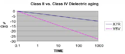
รูปที่ 4 - X7R เทียบกับ Y5V MLCC การเสื่อมสภาพของอายุอิเล็กทริกเซรามิกของความจุ
บทสรุป
แม้ว่า MLCC จะเป็นอุปกรณ์ที่ทรงคุณค่าในการออกแบบอิเล็กทรอนิกส์สมัยใหม่ แต่ก็ต้องเข้าใจข้อจำกัดของมัน ไม่เหมือนกับเทคโนโลยีคาปาซิเตอร์อื่น ๆ ผู้ออกแบบจำเป็นต้องทำความคุ้นเคยกับอุณหภูมิ ไบแอส DC และข้อกำหนดด้านอายุในการใช้งานที่ตั้งใจไว้อย่างใกล้ชิด จากนั้นจึงจะสามารถตัดสินใจเลือกวัสดุไดอิเล็กตริก ขนาดเคส และโทโพโลยีวงจรที่เหมาะสมได้
ที่มา:EPCI


ลิขสิทธิ์ © Xiamen Sinuowei Automated Science and Technology Co., Ltd. สงวนลิขสิทธิ์.

บริการออนไลน์
 ภาษา
ภาษา English
 français
 Deutsch
 русский
 italiano
 español
 português
 العربية
 日本語
日本語 한국의
한국의 ไทย
ไทย 中文
中文